keypad_to_microcontroller.md 17 KB
Keypad Scanning
There's a dozen ways to connect a keyboard to a microcontroller, and this paper attempts to enumerate many of them. There are similar articles on the internet [see below], but this paper introduces some new techniques: row-grounded, row-grounded-with-diodes, row-grounded-with-4-diodes and the sample code
Some articles focus on a full-function, unambiguous keyboard, where multiple key-presses can be detected. Something like a piano keyboard needs this, because multiple-keypresses are inherent to the task. This paper focuses more on the pre-wired 3x4 and 4x4 membrane keyboards that are cheaply available like this; these keypads are only appropriate for tasks which can live with a "one keypress at a time" limitation. Sometimes, this is appropriate if the keypad is small or in an awkward location, inherently limiting the user to a single finger press.
Terminology
In this document, n refers to the number of keys that are in the keyboard. The letter k refers to a specific key that is being pressed during an explanation.
One per Pin
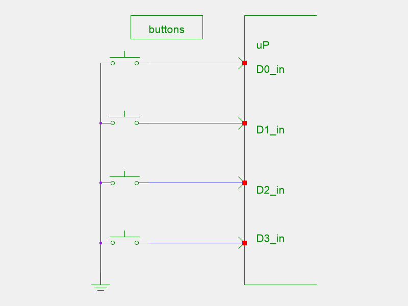
The simplest way to connect keys to a microcontroller is one key to one pin. Connect the other side of the key to ground. In your software, change all the pins to have a "pullup" and to be "inputs"
In idle, all the pins will read as a logic "high" or a 1. When a key is pressed, it will change to a "low" or 0.
This configuration has a few advantages:
- zero, one or any number of keys can be pressed simultaneously with out ambiguity
- there is no keyboard scan....which helps keep scan-noise out of the power supply; helpful in an audio environment
- can easily be set to wake-on-interrupt, which means that you can power down between keystrokes
See KeyBounce below.
Of course, this solution does not apply to a keyboard which has rows and columns.
Resistor Ladder
The other extreme is to only use a single input pin. There's a couple of ways to implement this.
Single Chain
By connecting the keys to different taps on a resistor ladder, you can supply different voltages to a common pin. Most microcontrollers have an A/D converter, and that can be used to determine which tap was connected.
A naive approach would be to simply use equal-valued resistors, and then each tap would be k/(n+1) of the supply voltage.
3x4 Chain
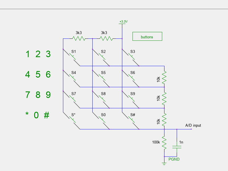
Sometimes a keyboard will be pre-wired as a grid, so you don't have access to the individual keys. You can still use the resistor ladder to determine the key-press.
When no key is pressed, the 100k resistor will pull down the CPU pin to 0V.
When a key is pressed, the CPU pin will rise up to a certain voltage, according to the following chart. Let's assume that Vcc = 3.3V.
| key label | calculation | value |
|---|---|---|
| # | 3.3 * 100k/100k = | 3.30V |
| 0 | 3.3 * 100k/103.3k = | 3.19V |
| * | 3.3 * 100k/106.6k = | 3.10V |
| 9 | 3.3 * 100k/110k = | 3.00V |
| 8 | 3.3 * 100k/113.3k = | 2.91V |
| 7 | 3.3 * 100k/116.6k = | 2.83V |
| 6 | 3.3 * 100k/120k = | 2.75V |
| 5 | 3.3 * 100k/123.3k = | 2.68V |
| 4 | 3.3 * 100k/126.6k = | 2.61V |
| 3 | 3.3 * 100k/130k = | 2.54V |
| 2 | 3.3 * 100k/133.3k = | 2.48V |
| 1 | 3.3 * 100k/136.6k = | 2.42V |
The smallest band is 0.06V, so an 8bit ADC would still have enough resolution (just barely) to determine which key was pressed. A 10 bit or 12 bit A/D converter will have no problem with these bands, even with 5% resistors.
The sense voltages are designed to all be above the halfway point, so that the idle CPU pin can be programmed as a logic input, and have interrupts enabled. Once a logic "high" is sensed, the CPU pin can be changed to an A/D pin, and the voltage measured (after a short pause). The 1nF capacitor helps with keyboard debounce; the time constant is ~10us.
Of course, if the user presses multiple keys simultaneously, the measurement will correspond to the highest voltage on that chart.
The same logic can be applied to a 4x4 keypad matrix, using 2.2k and 10k resisters over a 100k base. The center voltages will be 2.42, 2.46, 2.50, 2.54, 2.61, 2.65, 2.70, 2.75, 2.83, 2.88, 2.94, 3.00, 3.10, 3.16, 3.23, 3.30, which is should be fine for a 10 bit A/D.
In both cases, the resistors being identical allows the designer to use a multi-resistor pack.
See also this article
Scanning
3x4 Scanning
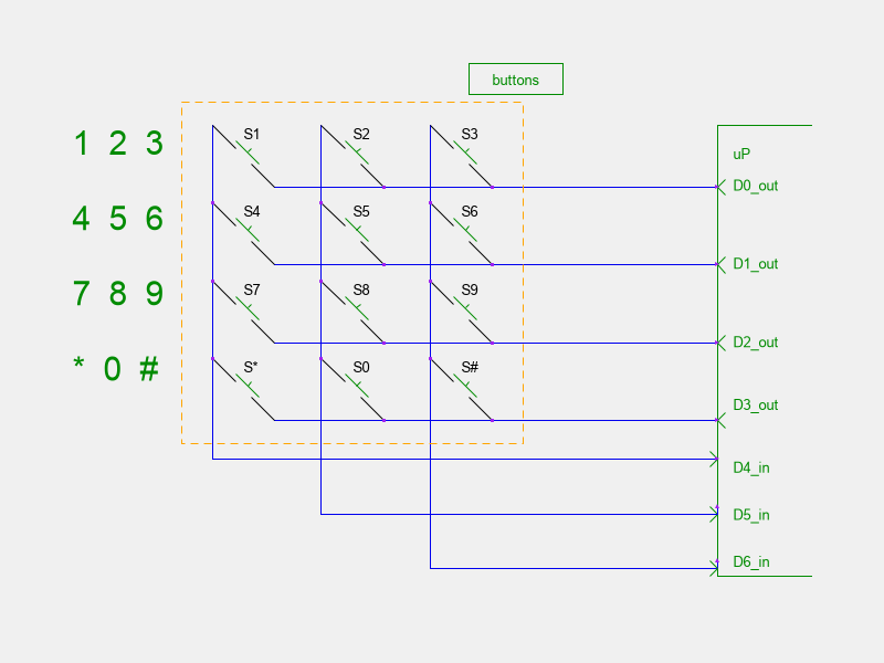
The simplest connection of a 3x4 keyboard is to simply use 7 GPIO pins, 4 for the rows, and 3 for the columns. Enable input & pullups on the columns and rows. At scan time, assert each row pin, one at a time, as a low, and measure the column inputs.
Example
D4..6 as the columns, D0..3 as the rows. Assert all as input+pullup. At scan time, assert D0 as output=0, measure D4..D6. Then restore D0, and assert D1 as low. Measure D4..D6 again. Repeat for D2 & D3.
You then have 4 measurements of 3 pins each. Any detected 0's on those inputs indicate a key-press.
This method allows you to determine 0, 1 or 2 keypresses; any combination of more keys may be ambiguous, and should be ignored.
The logic for a 4x4 keyboard is the same; it uses 8 GPIO pins.
This scheme can be configured for interrupt triggering [see interrupts] if the row pins are set to outputs, all=0, and the columns are set to input+pullup+interrupt. Any keypress will then pull at least one column line low. Once the interrupt is triggered, change to the logic described above, scan the keyboard [over the debounce period and then restore they keyboard to the "ready-for-interrupt" configuration.
3x4 plus Ground [new design]
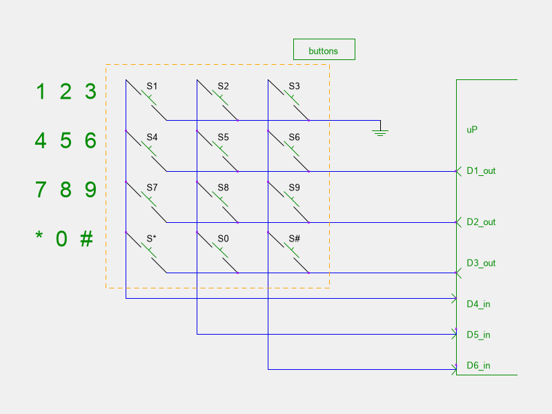
If you are really tight on pins, you can ground one of the rows and still get a functioning keyboard.
However, you can no longer determine if someone is pressing 2 keys at the same time. For example, pressing the "1" and "4" keys simultaneously will mask the "4" key.
This configuration also can be used as an interrupt-triggered keyboard.
The software scan for this configuration is basically the same as the previous section:
- set all rows to input+pullup; read the columns
- set D4 to output=0; read the columns
- set D5 to output=0; read the columns
- set D6 to output=0; read the columns
The resulting 4 groups of 3 bits indicate the state of the keyboard; 1=open, 0=keypress.
Again, the same logic will allow you to manage a 4x4 keyboard with 7 GPIO pins.
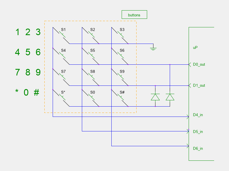
3x4 plus Ground and 2 Diodes [new design]
Again, we can scrape off one more GPIO if we can add a pair of diodes to the row pins.
The software is a little more complex, and depends heavily on the one-keypress-at-a-time assumption.
- set all rows to input+pullup; read the columns
- set D0 to output=0; read the columns
- set D1 to output=0; read the columns
- set both D0 and D1 to output=0; read the columns.
The columns have been read 4 times, 3 bits each.
If a column bit was pulled low when D0/D1 are both idle, then we know the key is in the first row. If a column bit is pulled low only during D0, we know it's in the 2nd row. D1 means the third row. If a column is pulled low for both D0 and D1 active......we know that it must be in the 4th row; the diodes act like an OR function.
For illustration, let's watch D4 as we cycle through D1/D0 = 11/10/01/11
- D4=1.1.1.1 no keypress
- D4=0.0.0.0 "1"
- D4=1.0.1.0 "4"
- D4=1.1.0.0 "7"
- D4=1.0.0.0 "*"
Putting together the whole keyboard, these are the values that each key will present to D6/D5/D4 as we cycle through D1/D1 = 11/10/01/00
| key press | D6 D5 D4 after D1D0=11.10.01.00 | octal |
|---|---|---|
| none | 111.111.111.111 | 7777 |
| 1 | 110.110.110.110 | 6666 |
| 2 | 101.101.101.101 | 5555 |
| 3 | 011.011.011.011 | 3333 |
| 4 | 111.110.111.110 | 7676 |
| 5 | 111.101.111.101 | 7575 |
| 6 | 111.011.111.011 | 7373 |
| 7 | 111.111.110.110 | 7766 |
| 8 | 111.111.101.101 | 7755 |
| 9 | 111.111.011.011 | 7733 |
| * | 111.110.110.110 | 7666 |
| 0 | 111.101.101.101 | 7555 |
| # | 111.011.011.011 | 7333 |
Here is some example code to illustrate this decode; in C; look for the symbol FIVE_PIN.
This configuration is also interrupt-capable, by setting the row drivers to output-low, and the columns as input+pullup+interrupt.
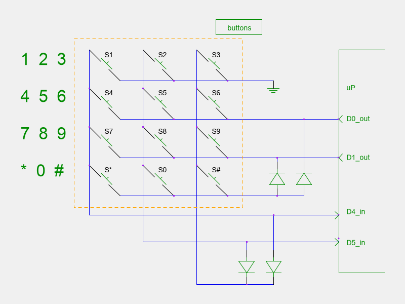
3x4 plus Ground and 4 Diodes [new design]
As an extreme, you can decode a 3x4 keypad with only 4 GPIO pins, using 4 external diodes. The decode logic is somewhat obtuse, and multiple-keypresses are not handled at all.
There are two row drivers, with one row connected to ground, and the 4th row connected to a diode pair, as in the previous section.
There are 2 column sensors, with the 3rd column connected to a diode pair.
A 4x4 matrix can be decoded with only 5 GPIO pins and 4 diodes.
Because there are several keypresses that involve 2 diodes in a row, I strongly recommend using Schottky key diodes, although I have built several test rigs with regular 1N4148's and had no problem interfacing to ESP8266. Schottky diodes are not much more expensive than regular diodes.
To illustrate the operation of this keyboard, follow the logic of the previous section. This time, there are only 2 column inputs to observe. So you get 4 observations of 2 pins; this can neatly be squeezed into a byte, so the table below shows 4 observations of D5/D4 squeezed into a byte.
| key press | D5 D4 pattern after D1D0=11.10.01.00 | hex |
|---|---|---|
| none | 11.11.11.11 | ff |
| 1 | 10.10.10.10 | aa |
| 2 | 01.01.01.01 | 55 |
| 3 | 00.00.00.00 | 00 |
| 4 | 11.10.11.10 | ee |
| 5 | 11.01.11.01 | dd |
| 6 | 11.00.11.00 | cc |
| 7 | 11.11.10.10 | fa |
| 8 | 11.11.01.01 | f5 |
| 9 | 11.11.00.00 | f0 |
| * | 11.10.10.10 | ea |
| 0 | 11.01.01.01 | d5 |
| # | 11.00.00.00 | c0 |
Notice that any keypress will involve at least one zero, so this configuration can be interrupt driven, by asserting D1=D0=low. Of course, once a key triggers and interrupt, the D1 and D0 must be set to pullup (high) so that the scanning can happen.
Here is some example code to illustrate this decode; in C;
look for the symbol FOUR_PIN. Here is a working prototype. 
Interrupts
These small keypads can be scanned continuously; you probably want to revisit the keypad every 50ms or so to make sure you don't miss any keypresses.
Changing to an interrupt-driven scheme allows you to relax about missing any keys; you are guaranteed to get an interrupt on each key press. It also allows you to power down the system until a key is pressed.
Most of the designs above allow for an interrupt-driven configuration. Simply set the column pins as "input-pullup-interrupt".
Bear in mind: if the user presses a 2nd key while the 1st key is still depressed, an interrupt will not be generated.
Keyboard Debounce
When a key is pressed, there is a short time during closure when the physical elements almost-touch, and the input pin may measure 1 or 0, even bouncing between them, until the key fully closes. For mechanical and elastomer switches, this may last as long as 1-5ms. The only switch that may not bounce would be an optical switch, but even then, unless the sensor has hysteresis, it may bounce as well.
Elastomer keys may also exhibit a slow contact phenomena, where the resistance if the key drops from infinity down to a few hundred ohms over a period of 5msec.
There are several ways to handle debouncing, some illustrated here:
https://my.eng.utah.edu/~cs5780/debouncing.pdf
https://dygma.com/blogs/stories/switch-bounce-and-debounce-delay
https://www.eejournal.com/article/ultimate-guide-to-switch-debounce-part-1/
In general it comes down to postponing the decision about which key is pressed until the bouncing has finished. You may average several observations, or simply delay ~5ms and read the final result.
Similarly, bouncing may happen at key-release time, but the duration of that bounce will almost certainly be shorter.
Other Techniques
Hackaday hackaday.com has some articles on alternative techniques.
One involves using an SPI output and a shift register
https://hackaday.com/2015/04/15/simple-keypad-scanning-with-spi-and-some-hardware/
This design requires an external chip ($0.10), 8 diodes and 4 resistors.
Reading DIP switches
In some situations, it's helpful to read an array of DIP switches, perhaps to read a configuration at power-on. In this case, there's no need for keyboard debounce. The read can be done with a parallel-to-serial device (74HC165 $0.08), or even a serial-to-parallel device, (74HC595 $0.10).
Multikey Presses
Of course, if you have wired your project for one-gpio-per-key, then there is never a problem with multiple key presses.
The 3x4 and 4x4 keypads are are available on the market do not have diodes at the grid junctions, and it is impossible to disambiguate certain key presses. For example, if "1" & "2" are pressed (R1, C1 & C2 are shorted), clever software can determine that this is the case. But if "1", "2" and "4" are pressed, then R1, R2, C1 and C2 are all shorted, and it's impossible to determine if the "5" key is pressed or not. Diodes are required at each junction to disambiguate.
External keyboard processor
With the current cost of processors, consider adding an external coprocessor to your project.
- with a few dozen I/O pins, lots of keys could be connected, without the need for key multiplexing
- this would also allow interrupt-driven keyboard response
- the external processor can do the keyboard debounce
- optionally, you can load this external CPU with extra tasks -light LEDs -drive watchdog circuitry -manage power-up/power-down sequencing that the main CPU may not be able to handle -manage narrow-duty-cycle master CPU (perhaps a WiFi CPU) in order to optimize battery drain
For example, the PY32F002AF/Cortex-M0+ is currently USD$0.10, and has 18 GPIO pins, each with pullup capability. You could easily connect 16 pins and still have Tx/Rx serial to report to your project-master CPU. This processor only sucks 1mA while running, so it's not a big part of your power budget.
(The next one down is the PY32F002AW with 14 PGIO, and the PY32F002AA with 8 GPIO)
At the low extreme, the CH32V003J is an 8 pin device with 6 GPIO pins. One could use 4 pins to interface to a 3x4 keypad, and still have 2 pins to send back decoded key information, over a 2/3 wire bus. It's U$0.11, 16k flash, 2k ram, 6gpio, sop8.
Summary
| name | # pins | simultaneous keys | extra components |
|---|---|---|---|
| one per pin | n for n | n | no |
| resistor ladder | 1 | 1 | n resistors |
| classic scan | 8 for 4x4, 7 for 3x4 | 2 | no |
| scan with ground | 7 for 4x4, 6 for 3x4 | 1 | no |
| scan with diodes | 6 for 4x4, 5 for 3x4 | 1 | 2 diodes |
| scan with 4 diodes | 5 for 4x4, 4 for 3x4 | 1 | 4 diodes |
External References
An excellent overview of keyboard scanning directly from a microcontroller.
https://ww1.microchip.com/downloads/aemDocuments/documents/MCU08/ApplicationNotes/ApplicationNotes/00003407A.pdf
Here is another excellent article:
http://www.openmusiclabs.com/learning/digital/input-matrix-scanning/index.html
I found the above at https://hackaday.com/2018/09/30/whats-the-cheapest-way-to-scan-lots-of-buttons/
Notes for the Hardware Design
ESP8266
I got burned on this. On many boards, the gpio15 has a pulldown resistor on board. And gpio16 does not have an on-chip pullup resitor. That makes it difficult to use these pins with the techniques above. FWIW.
Two Diodes
The final design above involves two diodes in series, and assumes that will present the GPIO pin with a logic "low". I measured a pair of 1N4148 diodes in series with 100uA going through them, and got 0.5V each, for a total of 1.0V presented to the GPIO. Many microcontrollers will accept that as a logic low, but some may not. (The ESP8266 documents a logic low as any voltage lower than 0.825V, an AtTiny threshold is 1.0 .....both @ 3.3Vsupply). The trouble starts when the abient temperature drops down -60C, each Silicon diode will rise by 0.13V, and the combination of both diodes will take it way out of detection range. So, if your keypad is going to be outside, definitely use Shottkey diodes.
