Small microcontrollers are often required to handle several tasks,
sometimes with overlapping phases. This paper will lead you through the
creation of a small operating system which can
be implemented on a tiny microcontroller, without the fancy time-slicing
that is offered by sophisticated operating systems like Linux and FreeRTos.
The core of this technique is covered in Part 1 of this paper. If you
just want to see how it all comes together, jump to Final Implementaion.
Part 2 contains enhancements and variations,
probably useful reading if you decide to adopt this programming
technique in your projects.
Intro
Abstract
This paper will take you through the creation of a tiny operating
system that can be implemented on a small microcontroller.
Audience
These techniques can be applied by anyone with experience in
C, Python or any
modern computer language. It helps to have a passing knowledge of how to
connect a transducer (button, LED, buzzer, etc) to a
microcontroller.
The Reality Check dropdowns in this article
provide extra, often practical supplementary reading.
Reality Check
The technique described here is also called event driven
programming.
This technique was used in the original Window (1995), including some
of the system calls:
sendMessage(), postMessage() and setTimer().
This event-driven technique is applicable to a whole host of small
microcontrollers, including
Some of the really tiny ones don’t have enough stack space to
implement these techniques (Puolop PB150, Padauk PxS15x, Bojuxing BJ8P,
Yspring MDT1x, EastSoft HR7P, Holtek Ht68.)
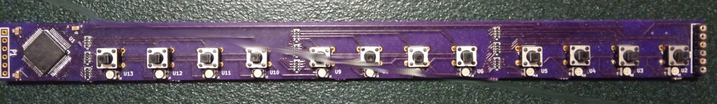
is a typical board hosting 12 buttons,
12 RGB LEDs, all hosted by an STM32. Every light and button can be
controlled separately and simultaneously, using the technique described
in this paper.
The Problem
Let’s suppose we want to flash an LED at 1 flash/2 sec, and
independently, respond to a push button by operating a different LED for
1.5 seconds. Both operations must operate separately. How do we
structure the code for the microcontroller to make this happen?
First Page
Let’s look an a pseudocode overview of what we want to do:
Of course, we will need to write the code for
setup_hardware() and setup_interrupts(). And
flashLedTask() and respondToButtonTask(). And
create the magic that allows event information to
flow. Don’t worry, it will all be laid out in the following pages.
If you’re concerned with complexity, feel free to jump ahead to the
final implementation page to see
real, tested, code.
Between here and there, I’ll walk you step-by-step through building
the structure and implementation.
This paper continues after that though, to show you how to expand
upon a build as the project-definition changes. There are also several
examples of state machines, and some discussion of practical matters,
refactoring and project structure.
Interrupts
In order to have a responsive system, it would make sense to use the
interrupt capabilities of these small micrcontrollers.
In the task described, we need to respond to a button press. So let’s
connect the button to an input pin and enable it to repsond to a button
press with interrupt code.
We also need to keep track of time…..so let’s hook up a system timer
to another interrupt.
Each interrupt causes the execution of interrupt handler
code. For this project, it might look somthing like this:
enum{EVT_NONE, EVT_TICK, EVT_BUTTON};INTERRUPT timer_isr(void){ newEvent(EVT_TICK);}INTERRUPT button_isr(void){ newEvent(EVT_BUTTON);// see notes about button bounce and acknowledgement}
The interrupt handlers are both very simple. They just create a
unique event and let the system know about it. Next, let’s talk
about events.
Reality check
In some microcontrollers, interrupts must be acknowledged.
Sometimes that means setting a hardware flag to indicate to the device
that you’re ready for another interrupt of the same type. And in some
cases, there’s no need to ack. Specifically, the SYS_TICK interrupt in
the ARM Cortex processors does not need an ack, so the above
code example for timer_isr() is complete.
When a pushbutton or switch is connected to a microcontroller, the
first bit of activity will cause the interrupt and execute the
button_isr() code. However, real buttons produce about
5msec of bounce and this will cause subsequent interrupts
unless they are somehow filtered out. There are lots of ways to handle
bounce, and I’ll let you read about that
[elsewhere]](#debouncing). Most techniques boil down to either ignoring
subsequent interrupts (from the same button) for about 5 msec, or
disabling that specific interrupt until the 5msec has passed.
As a general rule, input pins should be observed either by
interrupt service routine (ISR), or scanned periodically by the timer
ISR. Outputs should be controlled in the task code, which we’ll
see below.
Events
An event in this context is a small bit of information that
appears asynchronously in the system. Implemented, it can be a
byte, or an int or an even larger structure. But in
these small microcontrollers, let’s use a byte.
volatile uint8 event;
These events will be created in interrupt level of the code,
and processed at the main level. We use the event object to
send information between these levels, so we have to mark it volatile.
In this paper, the word message and event are
equivalent. Message has the sense of “a bit of communication
from another part of the program” and event has the sense of
“something external just happened”. At this point in the design, they
both mean the same thing.
By convention, let’s use zero to indicate the absence of an
event/message, and non-zero to represent an event/message.
Reality check
For this project, let’s suppose the timer ticks happen every 10ms (100
per second).
So now we start to get an idea of what kind of information the
interrupt handler code generates. Now let’s look at how that
information gets sent to the rest of the code:
newEvent().
newEvent()
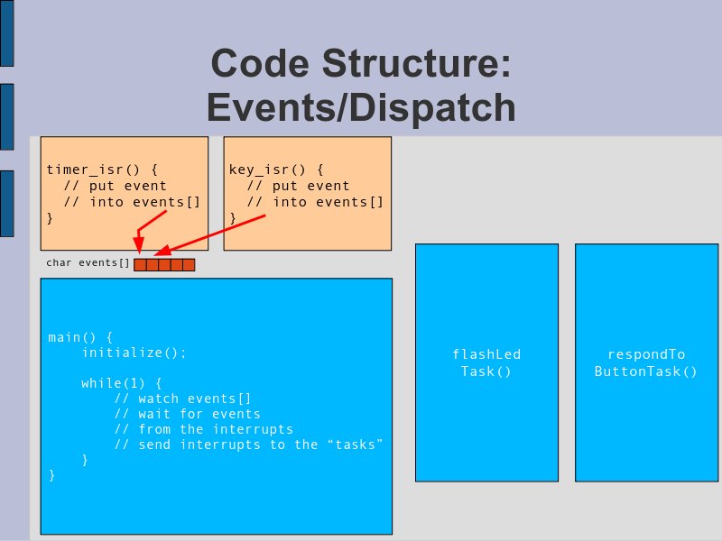
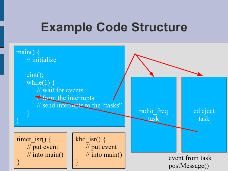
Here’s a block diagram of the message flow
How do we send the information (events/messages) from the interrupt
service routine to the main() code? We used shared
memory.
One way would be to have a global volatile uint8
location into which we drop the event information. But having
only one socket for that would be a bit naive; what happens if a timer
tick and a button press happen very close in time? What happens if the
timer tick events start to stack up?
It makes more sense to have an array:
volatile uint8 events[NUM_EVENTS] where NUM_EVENTS is on
the order of 5..10. That would give us 50-100msec to catch up in case
there’s a pileup of events/messages.
At the beginning, before anything happens, we need to make sure the
events[] is full of zeros (EVT_NONE), indicating that it’s
empty.
The newEvent(evt) routine simply adds the
evt to the array events[].
There is a problem with the above code. What happens if a
key_isr() is running, and is halfway through its call to
newEvent() when a timer_isr() happens, and
reenters the newEvent() routine. This will get really
messed up. So we need to wrap this particular code in a
critical section.
Here’s a more realistic version:
void newEvent(char evt){staticunsignedchar nextEvent;// keep track of where we are in queue disable_irq();// critical section events[nextEvent++]= evt;// insert event into queueif(nextEvent == NUM_EVENTS)// loop back to the start of queue nextEvent =0; enable_irq();// end critical section, probably <100us of blockage}
In the next section, we’ll show how the main() code
pulls the events out of the array, and leaves an EVT_NONE in its
place.
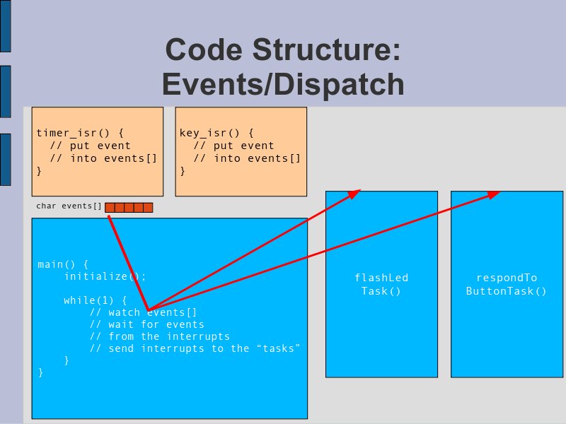
Dispatch
The main() code can simply watch the
events[] to see when an entry goes non-zero (!=EVT_NONE).
When that happens, main() will pull out the
event/message from the array, and call the task subroutines. In
this case, flashLedTask() and
respondToButtonTask().
To see the real code for the dispatcher, jump ahead.
Terminology
The main() code illustrated here calls the tasks as
subroutines, sending each one a copy of the event number.
As I mentioned earlier, events can also be refered to as
messages. We can also refer to this process “sending a message
to the task”
So, for this paper, these are equivalent
calling a task subroutine with the event information
sending a message to a task
Call task routines with
event
Reality check
It may seem wasteful to send all events to all
tasks. Probably some tasks don’t care about certain classes of events.
But classifying, sorting and filtering the events takes real time, and
code space, and probably isn’t worth it for these small
microcontrollers.
More sophisticated event systems do, in fact, filter and sort events.
For example, Windows only sends MOUSE_MOVE events to the
code belonging to the window over which the mouse is travelling. All the
other windows don’t get the event, speeding up the whole system.
Tasks
In this environment, the code that impliments a task is
simply a subroutine that accepts an event/message.
void taskCode(uint8 event){... process the event information ...}
The subroutine should be designed to flow-through as quickly as
possible, without any pauses/waits/delays.
If the problem that you’re trying to solve involves the passage of
time, or any delay, then you must break down the actions into individual
items, and build a state machine.
State Machine
A state machine in this environment is a subroutine which
can be called many times, and it remembers in which state it
was left from the previous call. Some invocations of this subroutine may
cause it to change state, which can be represented in a net diagram.
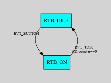
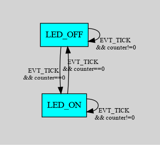
Here’s a state diagram for the task which reacts to a button press by
flashing an LED.
simple state diagram
How does the state code remember what state it’s in between
invocations? We can use a static variable. A
static is stored in main memory (not on the
stack), persists between calls and is initialized to zero.
The above diagram can be implemented in this code:
As you build the code from the diagram, I strongly suggest
that you use a switch(currentState) ....case STATE_1
approach to the task routine. If you try and code it with multiple
if(currentState==STATE_1), you will find yourself in a
tangle of spaghetti; and if you forget a critical else,
nothing will work as you expect.
if(state==1){if(event = EVT_1){ P3OUT =27;// turn on some hardware state =2;// and change state}}if(state==2){// <<<----- BAD BAD P3OUT =14; state =3;// <<<--- dont' change state twice in the same event}...
rather
switch(state){case1:if(event = EVT_1){ P3OUT =27;// turn on some hardware state =2;}break;case2: P3OUT =14; state =3;}...}
As a general rule, try to avoid changing states more than once per
event; this kind of discipline will help with debugging a complex
project.
Dispatcher Details
The last piece of the puzzle is the main() code which
observes the events[] array and calls the tasks.
The events[] array is designed so that a 0 means ‘no
event’, and the non-zero events are dropped into the array in order…so
pulling them out is pretty straight forward.
Each non-zero event is “sent” to each task…..by means of a subroutine
call. Once all the tasks have been invoked, the event is
thrown away and its slot in the array is set to zero.
Reality check
The main() code above needs to run with interrupts
enabled.
There’s lots of ways to structure the ‘wait for event’ loop. For
example, when you detect that the events[] array is empty,
you could power-down the microcontroller. In most microprocessors, an
interrupt will wake the CPU again, and deliver a non-zero event into the
array, so you might as well power-down while you’re waiting.
Final Implementation
Let’s put all of the above together, for an SMT32F Cortex M0, in
C code.
What’s missing from this code sample is the initialization of the
hardware……..some kind of setup() routine. I left it out
because it’s going to vary so much between processors, and only
distracts from the point of this paper. If you want a detailed, tested
copy of this code, see here
The above example only shows 2 tasks, so all the formal structure may
seem a bit silly. But once you have the infrastructure in place, you can
easily handle dozens of tasks, even on sub-$1 processors.
Part 2
Variations
Now that the infrastructure is in place, it’s easy to expand or
modify the code for changes in the project definition.
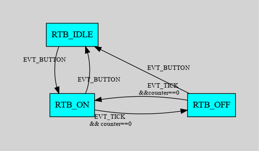
For example, suppose we want the respondToButtonTask()
to restart the LED timer on each key press:
Each of these diagrams corresponds to trivial changes in the state
code.
Working with Arduino
If you’re from the Arduino world, you have no doubt seen the
similarity between this OS plan and the Arduino infrastructure.
setup(){}// initialize and start up the devices and servicesloop(){}// code for continuous operation
You can certainly merge this paper’s operating system into the
Arduino architecture:
char events[];interrupt_service_routines(){ newEvent(evt);// insert events/messages into events[]}staticint nextEvent;void newEvent(char evt){}// same as above; put evt into the events[]setup(){}loop(){staticint nextTaskEvent;if(events[nextTaskEvent]!=EVT_NONE){// check for non-zero events[], task1(events[nextTaskEvent]);// and call the task routines task2(events[nextTaskEvent]); events[nextTaskEvent)= EVT_NONE;// free the slot, fill with 0if(++nextTaskEvent > NUM_EVENTS) nextTaskEvent =0;// and loop through the array}}void task1(char evt){}void task2(char evt){}
Tasks
The fundamental guideline for tasks is that they do not
stop. Control flows through and out the bottom, returning to the
dispatcher quickly.
Reality Check
In practical terms, if you have a timer tick that runs at every 10ms,
and about 5 tasks, then if you can keep each task under 2ms, you won’t
lose any events.
If a task occasionally runs into the 10’s of msec, the event queue
will handle buffering the events until they can be processed.
Under no circumstances should a task take more than 100msec. Use a new
state, and return from the tast. Process the new state later.
State Machine Examples
Car Window
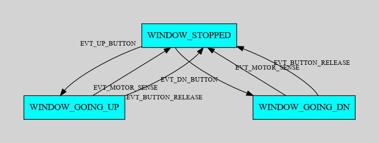
Suppose we want to control the power window on a car? For this
problem, we have an up/down button, a motor to drive the window up or
down, and a motor-overload sensor to detect when the motor is straining.
So the buttons & overload sensor are inputs, and the motor drive is
outputs.
When the user presses the “up” button, we should start the motor
moving upward. When the overload sensor detects a strain, then either
the window is all the way up….or it has encountered a finger or hand; in
either case, we need to turn the motor drive off.
Here’s a possible state diagram.
And here’s the matching code. Note the correspondence between the
diagram and the code: arrows leaving a state correspond to an
if() phrase.
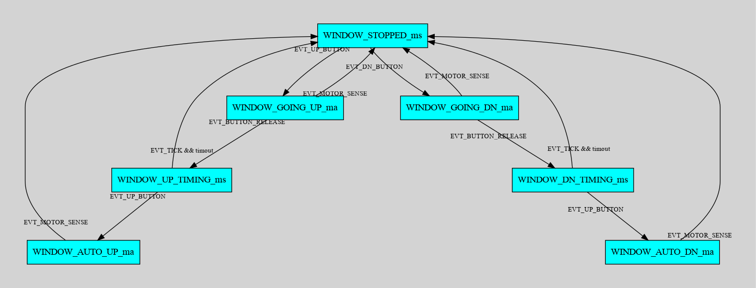
Now, suppose the problem definition is changed: if the user presses
the “up” button, the motor should only operate while the button is
pressed; stop on release. But if the user presses the “up” button a
second time within 1 second of the first release, the motor should drive
the window all the way up (auto-close).
Here is a possible state diagram. Notice the significant re-use of
code from the previous version.
window control with auto open/close,
(_ma) motor activated (_ms) motor stopped
Reality Check
This is such a simple task, with only a few I/O pins involved. In
theory, a cheap microcontroller could control a dozen windows, each
appearing to operate independantly.
In the code, one wouldn’t need to create a dozen tasks……just create
an index into the same code and invoke it in a way that makes it appear
as an independent task:
void main(void) {
  eint();
  while(1) {
    for (i=0; i<NUM_EVENTS; i++) {
      while (events[i]==EVT_NONE)
        {}
      taskWindow(events[i],0);
      taskWindow(events[i],1);
      // ...
      taskWindow(events[i],NUM_WINDOWS-1);
      events[i] = EVT_NONE;
    }
  }
}

// window management task
int windowState[NUM_WINDOWS];
void taskWindow(char event, int windowIndex) {
  // find the state from the windowState[windowIndex]
  // run through the state machine
  // any I/O will require an array of I/O addresses, use 'windowIndex'

  switch(windowState[windowIndex]) {
    case WS_IDLE:
      ...
      ...
  }
}
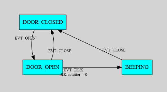
Fridge Door
A simple state machine can control the interior light of a fridge.
Here’s the use-case:
The problem has one input (door open) and two outputs (light and
audible alarm). If the door is open, turn on the light and start a timer
for 90 seconds. If the door is still open at the end of the 90 seconds,
start an audible alarm. If the door closes, stop the timer and turn off
the light and alarm. And if the door closes during the 90 seconds, turn
off the light.
Notice on the state diagram, the arrows heads and tails cluster, and
similar actions happen for multiple arrows. Perhaps we should write a
function that just deals with all the actions required when leaving or
entering a state. Then the task code would only have to manage the
arrows of the state diagram. Like this:
// this outer code deals with the arrows on the state diagramvoid fridgeTask(char event){switch(fridgeState){case FRIDGE_CLOSED:if(event == EVT_OPEN) changeFridgeState(FRIDGE_OPEN);break;case FRIDGE_OPEN:if(event == EVT_CLOSE) changeFridgeState(FRIDGE_CLOSED);if(event == EVT_FRIDGE_TIMEOUT) changeFridgeState(FRIDGE_BEEPING);break;case FRIDGE_BEEPING:if(event == EVT_CLOSE) changeFridgeState(FRIDGE_CLOSED);break;}}
while the inner code deals with the actions required for
entry and exit from each state
void changeFridgeState(char newState){staticchar oldState = FRIDGE_CLOSED;// do all the state-leaving actionsswitch(oldState){case FRIDGE_CLOSED: set_io(LIGHT, ON); setTimer(FRIDGE_TIMER, FRIDGE_OPEN_LIMIT);break;case FRIDGE_OPEN:break;case FRIDGE_BEEPING: set_io(ALARM, OFF);break;}// change state fridgeState = oldState = newState;// and do the state-entry codeswitch(newState){case FRIDGE_CLOSED: set_io(LIGHT, OFF); setTimer(FRIDGE_TIMER,0);break;case FRIDGE_OPEN:break;case FRIDGE_BEEPING: set_io(ALARM, ON);break;}}
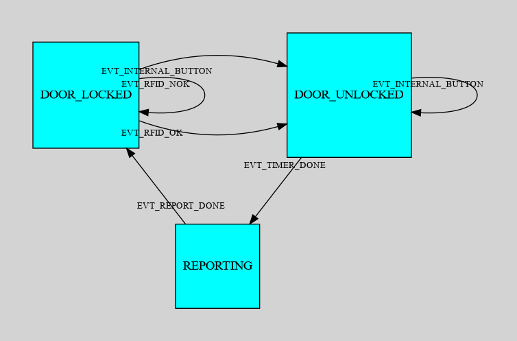
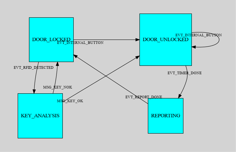
Door Opener
Suppose we have a power lock on a door, using a solenoid, and an RFID
tag detector on the “outside” and a push button on the “inside”. There
is also a WiFi connection to a server, by which we report door openings.
When the RFID tag sends us a message, it will contain a serial number.
If the number matches a known record, then operate the door-opener
solenoid for 4 seconds. If the “inside” button is pushed, operate the
door-opener for 4 seconds; if the “inside” button is pressed during the
4 seconds, restart the 4 second timer.
After the door is locked, send a report to the master control via the
WiFi.
Here’s the state diagram:
RFID operated door lock
I use EVT_ type events to indicate that they originate
in hardware, probably at the interrupt level; and MSG_ type
events to indicate they come from a software source, perhaps a sibling
task.
Suppose now that the serial number needs to be verified by a central
service. So when an RFID tag is detected, send a request to the master
control and wait for an ACK or NAK response. In the case of an ACK, open
the door solenoid for 4 seconds. The rest of the problem is as stated
above.
Here’s the modified state diagram:
RFID operated door, with remove key
verify
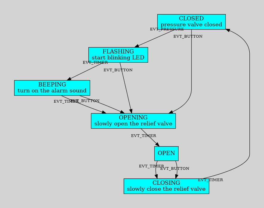
Beer Vat
Suppose we have to move a servo motor to lift the lid from a brewing
vat, to release excess pressure.
If high pressure is detected, flash the LED for 10 seconds, then
operate the beeper for 5 seconds, then operate servo; hold it open for 5
seconds and return the servo, LED and beeper to idle.
If the manual operation button is pressed, go directly to “operate
servo” as above.
If the manual button is pressed while the lid is open, close
immediately.
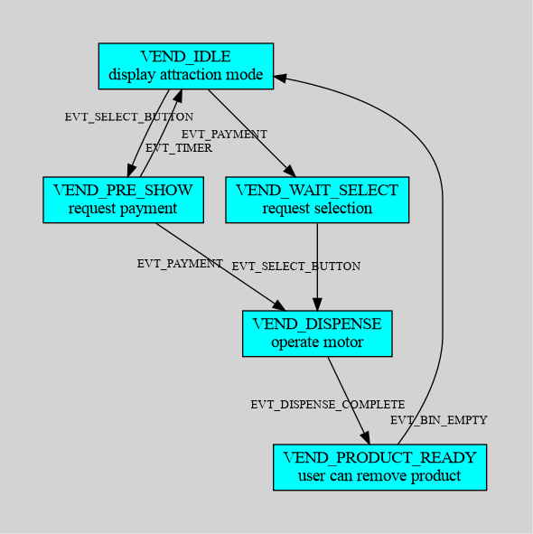
Vending Machine
When idle, wait for payment tap. If selection button is pressed
before payment, display cost to inform the user for 3 seconds.
After payment tap, request the user select item.
Operate dispense motor.
Wait for object to be removed from output bin.
states for vending machine
Events
In all the above, events were implemented as a simple
unsigned char, allowing 255 different event types.
There’s no reason we couldn’t use an unsigned short or
even an int. Further, a 16 bit event number could be
designed to be 8 bits of event type, and 8 bits of supplementary event
information:
typedefstruct Event {unsignedchar type;unsignedchar info;} Event;Event e ={MSG_KEYPRESS, KEY_A};
In the old Windows system, events/messages were realized as
a 16 bit number, with an extra 32 bit number glued to it for extra
information.
typedefstruct MSG { UINT message; LPARAM lParam;};// some extra detail removed
For example, WM_CHAR=0x0102 indicates that a key was
pressed, with the extra 32bit lParam carrying the
information about which key.
Timers
The simplest state timer is made with a static variable associated
with the state code.
To start the timer, simply initialize the static variable. On timer
ticks, decrement (or increment if you prefer) this variable until it
hits a limit, and then make a state change.
For instance, to create a timer that waits 100 timer ticks, you could
use:
staticint state;staticint stateTimer;void stateCode(char event){switch(state){case STATE_IDLE:if(event = EVENT_TRIGGER){ stateTimer =100; state = STATE_DELAY;}break;case STATE_DELAY:if(event = EVENT_TICK){if(--stateTimer ==0){// the timer is finished state = STATE_NEXT;}}break;// ....}}In the above example, you could equally well have set the timer to start at zeroand increment until it hits the desired limit (100 in this case).In a moderate sized project, timers like this will proliferate throughout the code,making it awkward to read. One solution to this is to centralize the timers.In all the above examples, the `timer_irq()` code is trivial, just `newEvent(EVT_TICK)`.Suppose we add code to the `timer_irq()` so that it can process timer counting onbehalf of the tasks......### Timers as a ResourceLet's create a centralized service called `setTimer(timer_index, timer_count)`. A task can call this service with a unique `timer_index` and a requested count. The`timer_irq()` will then count out the ticks on behalf of the task, and when the tickcount is finished, the `timer_irq()` code can generate a unique event, perhaps`EVT_TIMER_n`.So the state code can then look something like this:```Cstaticint state;void stateCode(char event){switch(state){case STATE_IDLE:if(event = EVENT_TRIGGER){ setTimer(TIMER_1,100); state = STATE_DELAY;}break;case STATE_DELAY:if(event = EVENT_TIMER_1){// the timer is finished state = STATE_NEXT;}}break;// ....}}
This makes the state code much simpler to read, hiding all the
increments/decrements and limit testing.
The overhead for this ends up in the timer_irq() code,
and might look something like this:
staticunsignedint timers[NUM_TIMERS];#define EVT_TIMER_OFFSET 100enum{EVENT_TIMER_1=EVT_TIMER_OFFSET, EVENT_TIMER_2, EVENT_TIMER_3};// 100, 101...enum{TIMER_1, TIMER_2, TIMER_3};// 0,1,2,....void timer_irq(){ newEvent(EVT_TICK);// the main tick, fires every timefor(i=0; i<NUM_TIMERS){// the system timers, fires on completionif(timers[i]>0){if(--timers[i]==0) newEvent(i + EVT_TIMER_OFFSET);}}}/* common service, available to all tasks */void setTimer(int timerIndex,unsignedint timerCount){ timers[timerIndex]= timerCount;}
Reality Check
On a typical microcontroller running at 24MHz, with 5 timers, this
adds about 2 microseconds of extra time to the timer_irq()
code, which typically runs every 10 or 100msec. It considerably
simplifies the task code, makes it more legible and probably reduces
bugs that may appear by duplication of code.
Another possible design for timers is to have the main
timer_isr() increment a global atomic
voloatile int timer variable, and the tasks can observe
this timer and set a target based on that.
volatileint timer;// on most microcontrollers, access to an int// will be atomicINTERRUPT timer_isr(void){ timer++; newEvent(EVT_TICK);}// .... state code ...staticint targetTime;void stateCode(uint8 event){switch(state){case STATE1://..... set a target targetTimer = time + DELAY_TIME; state = state2;//.....case STATE2:if(event == EVT_TICK){if(time == targetTimer){//.... we've waited long enough}}//...}}
Real Code
Here is an example of a complete and tested project on a small
STM32F030 board. Open all the little arrows to see the complete
code.
board specific defines
#include "stm32f030.h"/****** project hardware ******/// on this demo board, there is a push button on PB13 and// an LED on PA4 and PF5#define LED 0x10// port A bit 4 these LED are LOW=lit-up#define LED2 0x50020// port F bit 5GPIO_TypeDef * GROUP[]={GPIOA, GPIOB, GPIOC, GPIOD,0, GPIOF};// 0,0x10000,0x20000, etcvoid gpio_set(uint32 bitPosition,bool value){ vu32* group =&((GROUP[bitPosition >>16])->ODR); bitPosition &=0xFFFF;if(value)*group |= bitPosition;else*group &=~bitPosition;}
/***** events ****/#define NUM_EVENTS 10volatile uint8 events[NUM_EVENTS];enum{ EVT_NONE, EVT_TICK, EVT_BUTTON};void newEvent(uint8 e);/********** tasks ***********/void ledTask(uint8 evt);void respondToButtonTask(uint8 evt);/********** interrupts **************/volatile uint32 tick;// increasing at 100 ticks/sec// takes a year to roll-overvoid timer_isr(void){ tick++; newEvent(EVT_TICK);// this interrupt is auto-ack'd}void button_isr(void){ newEvent(EVT_BUTTON); EXTI->PR |=0x3001;// ack it }/** newEvent * add the event to the event queue * wrapped in critical section * * @paramthe event */void newEvent(char e){static uint nextEvent; dint();// critical section events[nextEvent++]= e;if(nextEvent==NUM_EVENTS) nextEvent =0; eint();}
hardware initialization
/***** init ******//* called by newlib startup */void _init(void){// startup code// use default clocks// turn on all the GPIO's RCC->AHBENR =0x005e0014;// enable SysCfg RCC->APB2ENR =0x00004801;// enable the two LEDs as outputs GPIOA->MODER =(GPIOA->MODER &0xFFFFFCFF)|0x00000100;// port A bit 4 GPIOF->MODER =(GPIOF->MODER &0xFFFFF3FF)|0x00000400;// port F bit 5// and the push button as input + pulldown GPIOB->PUPDR =(GPIOB->PUPDR &0xF3FFFFFF)|0x08000000;// pulldown on 13// keep the clocking system simple: just use the 8MHz HSI everywhere SysTick->LOAD =10000;// 10 msec SysTick->VAL =0; SysTick->CTRL =3;// count at 1usec, use interrupts/* to configure an interrupt on the stm32f0xx, - enable the EXTI->IMR for the pin - set EXTI->RTSR for select rising edge - set the SYSCFG->EXTICRx pin to route it - enable the gating bit in the NVIC register - don't forget to ack each interrupt at EXTI->PR */ EXTI->IMR =0x2000;// enable interrupt from line 13 EXTI->RTSR =0x2000;// interrupt on rising edge SYSCFG->EXTICR[3]=0x0010;// select prot B for exti-13 NVIC->ISER[0]=0x00E1;// enable in NVIC: gpio & watchdog}
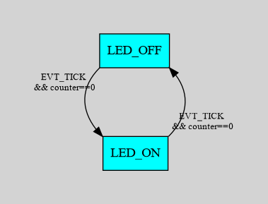
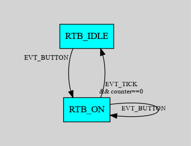
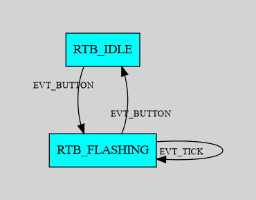
For things like flashing LED’s, you could create two states, and
toggle between them, like this:
Or, you could simply have an internal (static, not-on-the-stack)
variable which can keep track of the LED toggle. The state diagram then
simplifies:
uint8 rtbState = RTB_IDLE;// major state, RTB_IDLE/RTB_FLASHINGuint8 rtbSubState = RTB_FLASH_OFF;// minor state, toggles LED on/off
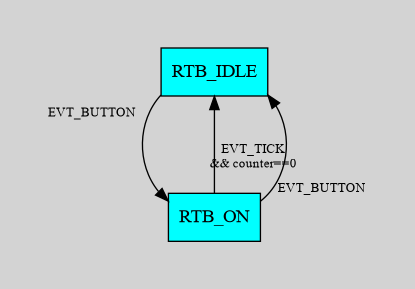
Alternatively, you could use the timer counter variable, and
make changes at the half-way point through the count. This simplifies
the substate design to this:
const uint16 FLASH_CYCLE_TIME 150;const uint16 FLASH_ON_TIME 40;uint8 rtbState = STATE_IDLE;void rtbTaskCode(char event){static uint16 flashCount=0;switch(taskState){case RTB_IDLE:if(event == EVT_BUTTON){ rtbState = STATE_FLASHING; flashCount = FLASH_CYCLE_TIME;}break;case STATE_FLASHING:// count down flashCount, toggle LED halfway throughif(event == EVT_TICK){if(--flashCount ==0){ setLED(OFF); flashCount = FLASH_CYCLE_TIME;}elseif(flashCount == FLASH_ON_TIME){ setLED(ON);}// ... make sure to turn LED off when leaving this stateif(event == EVT_BUTTON){ setLED(OFF); rtbState = RTB_IDLE;}break;}}}
State Machine Initialization
Notice that there’s no initialization of states in this code. It
would be very handy if we knew when to initialize all the
lights and buzzers and match up the various states. Perhaps the
main() code could add a single event into the event queue
at power-up, perhaps EVT_INIT. It might be added like
this:
void main(void){ newEvent(EVT_INIT);// early, before interrupts, so we know it's first in line eint();while(1){... dispatcher code ...}}
Then, in the state code, you can catch that event and set up whatever
might be required
uint8 myState;void stateCode(uint8 event){if(event==EVT_INIT){// ... do setup code myState = FIRST_STATE;return;}// ... regular state machine code}
Messages
Now that we have an event/dispatcher system, we can also also use it
to send information asychronously between tasks. For example, if a
keyboard processing task needs to inform its siblings, it can create
messages which can be injected into the event queue.
Notice the change of terminology, where message indicates
that the entry was created by code procesing, rather than an
interrupt.
PostMessage
We need a service routine to add messages to the event queue:
postMessage(). This call is very smimilar
newEvent() which should only be called from interrupts.
cd-eject task uses postMessage() to
broadcast a message
void postMessage(uint8 message);
Notice that postMessage can’t return any information,
because it’s not processed immediately; the message is added to
the event queue to be processed at a later time.
Reality Check
In this tiny system, postMessage() is exactly the same as
newEvent(). The reason that I use different names is that
some more sophisticated operating systems require that these two
functions are not identical.
SendMessage
In some cases we may want the sibling task to process the information
immediately. This means:
we can be assured that the sibling task has fully processed the
information
does not involve the dispatcher; but does require extra room on the
stack
we could get a return value from the sibling task; since
it’s implemented as a subroutine, it’s allowed to return a value
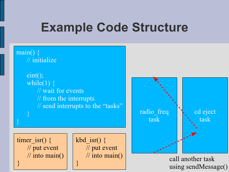
cd-eject task uses sendMessage() to call
a sibling task
This of course means that the prototype for task functions would
change from
Why might one want to send a message between tasks?
Suppose you have a rotary encoder, which sends quadrant signals,
which need to be interpreted as clockwise and counter
clockwise. You could have one task devoted to determining the
direction of the knob (and debouncing), and
have it send clean EVT_CW and EVT_CCW messages to its sibgling
tasks.
Another possible use of messages is to create alternate
souces of input. For example, a device which has a temperature set by
“up/down” buttons on a front panel could receive the same controls from
an infra-red remote, or even a serial port (perhaps for testing).
And why sendMessage()? Perhaps you need to have a
sibling task change states, or process information before you
continue in your task. Imagine there is a slave WiFi chip that needs to
be powered up before you send it a request….you could use
sendMessage() to activate the power, and then continue,
knowing that your peripheral is available.
Ideas for Tasks
I taught this coding technique at the college level, and a typical
end-of-term assignment was to code up a simulated automobile
entertainment system, which included about 6-10 concurrent tasks:
task blue light to show bluetooth connectivity
volume up/down sense and display
radio channel select buttons
step single freq, or high-speed scan
power on/off management
remote control of volume/radio-select from the steering wheel (uart
link)
backlight for night-time viewing (auto sense from a light
sensor)
service-required LED, flashing
a beeper to confirm keypresses (30ms) and alarm (700ms/100ms)
a clock up/down set button
3 buttons: “set min/hr” and “+” and “-”
Each list item above corresponds to one task. My students were able
to code this up with about 35k of source, which compiles to about 8k of
code and 256B of RAM (on an STM32)
More State Machines
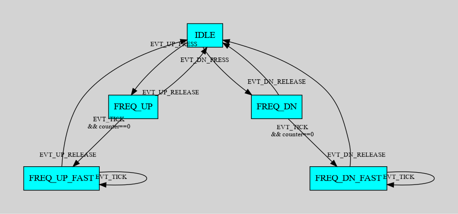
Radio Tuner
Suppose we have a + and - button for tuning
a radio. A press of either will move the radio frequency by one step. If
the button is held for more than 0.5 seconds, the radio should change to
a rapid scroll through all available frequencies.
Suppose we have events coming at 100msec, and that the radio
frequencies are 88.7 up to 107.9, with steps at 0.1. And finally,
suppose there are 5 available events:
 is a typical board hosting 12 buttons,
12 RGB LEDs, all hosted by an STM32. Every light and button can be
controlled separately and simultaneously, using the technique described
in this paper.
is a typical board hosting 12 buttons,
12 RGB LEDs, all hosted by an STM32. Every light and button can be
controlled separately and simultaneously, using the technique described
in this paper.